CAN Bus Integration for the M1502E-111 Direct Drive Motor
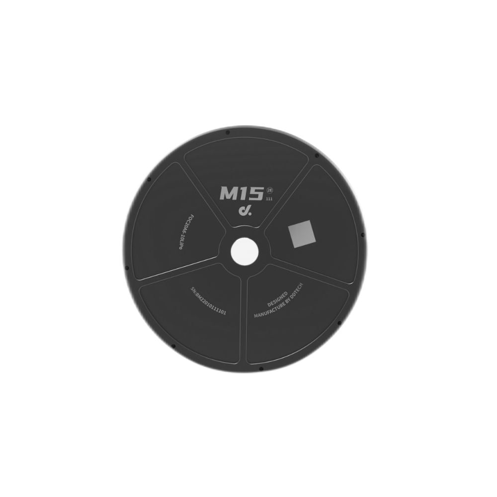
The M1502E-111 Direct Drive Motor becomes much easier to manage when connected through a CAN network. A standard CAN bus can connect multiple motors with only two communication wires, supports data rates up to 1 Mbps, and is widely used in robotics, AGVs, industrial automation, and medical equipment. Real-time feedback for position, speed, current, temperature, and fault status allows one controller to monitor every actuator continuously while reducing wiring, installation time, and maintenance work.
Modern robots often contain four, six, or even 12 motor axes that must exchange data within milliseconds. Using separate communication cables for every actuator increases installation time and makes future upgrades more complicated. CAN communication solves this by allowing every motor to share one communication line while keeping each device identifiable through an individual CAN ID. Since the protocol has been used in industrial equipment for more than 30 years, hardware compatibility and software support are widely available.
As the communication network grows, cable quality and network layout become more important. A CAN system normally uses twisted-pair wiring with 120 Ω termination resistors installed at both physical ends of the bus. At 1 Mbps, shorter cable lengths provide the best communication stability, while lower baud rates allow much longer cable runs. Industrial installations commonly select 250 kbps, 500 kbps, or 1 Mbps depending on cabinet layout and total cable distance.
One communication cable can carry motion commands, status messages, and diagnostic information for multiple motors at the same time without requiring separate serial ports for every actuator.
The M1502E-111 exchanges much more than simple start and stop commands. Typical CAN frames include target position, velocity, torque request, acceleration settings, operating mode selection, and enable or disable instructions. At the same time, the motor returns encoder position, actual speed, motor current, supply voltage, internal temperature, and fault information. Many motion controllers refresh this information every 10–20 ms, allowing operators to monitor system performance almost continuously.
The communication process also simplifies commissioning. Engineers usually assign a unique CAN ID to each actuator before configuring speed limits, torque limits, acceleration values, and protection settings. A six-axis robotic arm, for example, may contain IDs from 1 to 6, allowing the controller to address every joint independently while keeping all motors on the same physical network. This approach also reduces connector count compared with separate communication channels.
| Function | Typical CAN Data |
|---|---|
| Motion Control | Position, speed, torque |
| Motor Feedback | Encoder value, RPM, current |
| Health Status | Temperature, voltage, fault code |
| Configuration | CAN ID, operating mode, limits |
Once configuration is complete, synchronized motion becomes much easier. Mobile robots with four independent wheels can receive movement commands almost simultaneously, helping maintain smoother steering and more consistent speed. Multi-axis equipment such as inspection robots or automated handling systems also benefits because every actuator receives instructions through the same communication bus instead of different interfaces.
Communication timing becomes more consistent when every actuator receives commands from the same CAN network rather than separate serial connections.
Another benefit appears during maintenance. If one motor reports higher current consumption or an internal temperature above 80°C, maintenance staff can identify the affected actuator without disconnecting the machine. Historical operating information collected by the controller can also help compare performance between motors after hundreds or thousands of operating hours. Some facilities review communication logs every 500 operating hours as part of scheduled equipment inspections.
Reliable communication also depends on proper electrical installation. Shielded twisted-pair cable helps reduce electromagnetic interference, especially when power cables and communication cables are installed inside the same enclosure. Grounding should remain consistent across the system, and connectors should be secured to prevent intermittent communication. These installation practices are commonly recommended in industrial automation because they improve long-term communication stability.
The software layer is equally important. Most PLCs, industrial PCs, and embedded controllers already include CAN libraries that support message transmission, message filtering, error detection, and bus monitoring. Many robotics platforms also support higher-level protocols built on CAN, making integration faster for developers who need coordinated motion, safety monitoring, and equipment diagnostics within one control program.
For projects that require scalable motion control, the CAN Bus direct drive motorr offers a practical communication approach. Additional motors can usually be connected by extending the existing CAN network, assigning new CAN IDs, and updating controller parameters instead of redesigning the electrical architecture. This allows the same communication framework to support small prototypes, production equipment, autonomous mobile robots, warehouse automation, laboratory instruments, and precision positioning systems with consistent operating behavior.